
The Kinesys Elevation Drive v2 removes the need for large quantities of cabling and permits a number of motors and controllers to be supplied by single power and data cables.
The Kinesys Elevation Drive v2 together with customised versions of the most popular models of chain hoist, such as Lodestar, Liftket and GIS, represents the most flexible and reliable variable speed ‘open system’ available in the market.
Easy to install, simple to configure and with an ergonomic and compact design, it has the ability to ramp start, ramp stop, position and vary the speed of a chain hoist for maximum creative effect.
With the addition of a simple adapter cable, the converted motors can be used as standard fixed speed chain hoists allowing maximum flexibility of motor use.
The Kinesys Elevation Drive v2 can be controlled by K2 or Vector software packages and interfaces with other Kinesys products for a totally integrated show control system.
The Kinesys Elevation Drive v2 is available in both US and European voltage variants, with multiple fixings for hook clamps or half couplers which allow for a variety of mounting orientations.
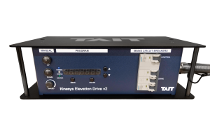
Kinesys Elevation Drive v2
-
Features
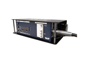
- 32A mains input and output connections all ‘daisy-chain’ operation
- Robust multipin connector for hoist connection – includes motor, brake, limit switch and encoder connections
- Remote control input allows full variable speed operation using a Kinesys pendant
- LED display, intuitive menu system and rugged manual control buttons allow for easy setup
Hoist Connection
- 5pin 32A ‘Ceeform’ type socket to IEC60309
Control Connections
- 7-pin male XLR connector with female link out
Hoist Connection
- 8+24-pin ‘Harting’ connector
Elevation1+ vs Kinesys Elevation Drive v2
In order to ensure continued availability of the popular Elevation drive despite global supply-chain challenges, we have re-engineered some of the internal components in this v2 of the drive. The Kinesys Elevation Drive v2 now incorporates a new VFD component, it will start and stop as expected, both accurately and on time, however there may be slight variations in speed during acceleration and deceleration when compared to a v1 unit.
To avoid any undesired outcomes caused by the differences in power delivery curves, it is not recommended to mix V1 and V2 drives when lifting the same object.
Additionally, the 4 pin XLR connector, which was previously included for an analogue load cell connection, is no longer available in the Kinesys Elevation Drive v2. This feature is now unnecessary when using the LibraPRO device.
Finally, we have made a change to the outer metalwork housing to reflect that Kinesys is a TAIT Company. The addition of the TAIT logo not only aligns the product with the TAIT Group’s branding, but also reinforces out commitment to delivering high-quality products that meet the expectations of our customers.
FAQ
-
03/12/2010
Elevation 1+ units contain a set of 7 motion parameters, these parameters help to define the movement charastics of the attached motor.
NOTE: Only adjust these parameters if you are confident of your abilities to tune the system. The Elevation 1+ is supplied with a default set of parameters which are designed to work in the vast majority of situations and environments. When tuning the drive be sure that the device and load are free and safe to move and that there is physical room to allow for unexpected movement and behaviour.
The 7 parameters are:
- Proportional Gain (Default 25000)
The proportional gain in the system creates an output that is proportional to the position following error (the difference between its current location and its ideal location). This gain is not affected by speed and ramps and provides the majority of the feedback require to keep the system working correctly.
- Integral Gain (Default 1500)
The integral gain creates an output that is proportional to the sum of the errors that have occurred during the system operation. Its effect is to reduce small steady-state position errors. Integral gain has most effect in ensuring that the desired speed is followed as accurately as possible and therefore applies most during the cruise phase of a move profile.
- Derivative Gain (Default 00250)
The derivative gain is a function of the measured velocity and improves the high frequency closed loop response. Derivative gain is the most volatile of the three settings. Its effect is most pronounced during the acceleration and deceleration phases of a move profile. An incorrect value for this setting can lead to instability during movement and potentially erratic behaviour.
- Min Drive Speed (Default 50)
The minimum raw speed value that can be sent to the drive. This value is measured in units of 0.02Hz. Used to set the minimum drive speed required to obtain movement. This value is used with the max speed output parameter to limit the range of the PID loop. The Elevation 1+ Firmware only uses the lower 16 bits as an unsigned integer.
- Max Drive Speed (Default 5000)
The maximum raw speed value that can be sent to the drive. This value is measured in units of 0.02Hz. Used to set the maximum drive speed that may be permitted. This value is used with the min speed output parameter to limit the range of the PID loop. The Elevation 1+ Firmware only uses the lower 16 bits as an unsigned integer.
- Pos Trip Difference (Default 300)
The PID servo control generates the correct move profile in software which the PID loop attempts to follow as closely as possible. Should the position leading or following error distance exceed this setting an over speed or under speed error will be generated and the move stopped. Firmware only uses the lower 16 bits as an unsigned integer.
- Brake Delay (Default 0)
If for any reason an Elevation 1+ looses it’s motion parameters or you wish to check to ensure an Elevation 1+ unit has the correct set of motion parameters, this can be done from the Channel Setup window in Vector. Under the Motion Parameters heading select each motion parameter from the drop down and the value will appear. Changing any of these values from the default (set by the motor personality) can cause unexpected behaviour by the motor and should not be done without prior consultation with Kinesys.
Lost Motion Parameters
If for any reason an Elevation 1+ looses it’s motion parameters or you wish to check to ensure an Elevation 1+ unit has the correct set of motion parameters, this can be done from the Channel Setup window in Vector. Under the Motion Parameters heading select each motion parameter from the drop down and the value will appear. Changing any of these values from the default (set by the motor personality) can cause unexpected behaviour by the motor and should not be done without prior consultation with Kinesys.
The signs that an Elevation 1+ has lost it’s motion parameter settings are that it will loose it’s address and once the address has been reset any attempted movement will cause an underspeed error.
This can be fixed either by using Vector as indicated above or via the front panel of the Elevation 1+, under the Setup/Parameters/ P1- P7 menu.
Ensure that you reset the offset parameters (Up and Down) back to 0, as these can also become corrupted if an Elevation 1+ has lost it’s motion parameters. -
22/07/2011
The ENC 2 error means that the Elevation 1+ is receiving encoder pulses in the wrong order.
This could be due to:- The encoder being wired incorreclly.
- The encoder has developed a fault.
- There is a fault in the Harting connector or it is wired incorrectly.
-
23/09/2010
Navigating the Setup menu on the Elevation 1+ unit shows a Fast option and a value in mm/second/second. This option is the rate at which the unit will decererate if it detects an internal fault such as “Overspeed” or “ENC1”.
When using Vector to programme Elevation 1+ units this value is automatically set to the maximum deceleration rate, specified in the motor profile. -
23/09/2010
Running power to Elevation 1+ units at 60hz will cause issues at 400v and above. If you are using a transformer, get it tapped to 380v and the Elevation 1+ units should run with no issues.
-
07/09/2010
The Kinesys Elevation 1+ is designed to comply with European legislation for variable speed drives, which require that an RFI (Radio Frequency Interference) filter is included to prevent the noise generated by the drive from interfering with nearby computer systems, radio equipment etc. The inverter drive within the Elevation 1+ is an independently manufactured product widely available within Europe and the US which incorporates the filtering required to comply with the European EMC (ElectroMagnetic Compatibility) directive 89/336/EEC. One of the consequences of including such a filter is a small current leakage to ground within each Elevation 1+.
The total ground leakage for a typical Elevation system may be in the region of 60-300mA, which will be more than sufficient to trip the 30mA RCD (Residual Current Device) fitted to many house rigging supplies within Europe. A single Elevation 1+ may also trip a sensitive RCD on power-up due to the charging of the internal capacitors – this is a common situation when using any variable speed drive.
As most moving lights, video screen power supplies etc. will also have a inherent earth leakage due to internal RFI filters nuisance tripping may increase when other equipment is turned on.
RCDs are set at a default level of 30mA as this has been found to be the point at which an RCD will trip before a current high enough to cause physiological damage will flow through the human body in the event of accidental contact – refer to IEC publication 479 “effects of currents passing through the human body” for further information.
Where a system has an inherent leakage, some protection may still be provided by setting the RCD at a level approximately 30mA higher than the system’s base leakage current – this will overcome the problem of nuisance tripping and yet still provide a degree of personnel protection.
Kinesys have addressed this issue by providing an adjustable RCD within the Array PD-ES power distribution. The adjustable RCD should be set to a point approximately 30mA higher than the point at which a full system trips on powerup – 100mA would be a good starting point. The time delay should always be set to minimum (30ms).
To set the RCD to 100mA the second DIP switch should be set to the “I∆ x 0,1” position; set the top left potentiometer to 1 to set a trip current of 100mA. Make sure the fourth DIP switch is in the “tx1” position and the right hand potentiometer is turned fully counterclockwise to set a minimum time delay of 30mS.
In any large power distribution system, for example a venue power supply which is distributed to various departments such as lighting, automation, sound etc, the ideal situation is for each service to be protected by its own RCD, set to provide the required level of protection. An overall RCD on the generator or incoming supply should be set to a current value higher than any of the downstream devices, and should also incorporate a time delay. With this system, a fault on a final circuit such as a hoist controller or video screen will still result in disconnection of the final supply but will not cause disruption to other departments. -
07/09/2010
These notes are intended to give experienced personnel additional information regarding PAT testing of Elevation 1+ controllers. They are not intended to form a complete guide to PAT testing of the equipment – consult your PAT tester instruction manual for further information.
Before testing
Make sure that the Elevation 1+ is disconnected from the supply and all other equipment (hoists, control systems etc.). Only qualified personnel should PAT test equipment – PAT testing can be hazardous and can result in equipment damage if not carried out correctly. The Elevation 1+ is a class 1 appliance.
Earth Bond Continuity Test
Do not apply the wander lead to any pins of the multipin hoist connector except pin 1 (earth), or to any part of the XLR control or data connectors.
A 25A earth bond continuity test may be carried out to any part of the case, and to the mains link out connector (“Ceeform”) earth. The earth connections to the multipin hoist connector (shell and pin 1) are only rated to 16A and may be damaged by a 25A test – use a 100mA test for these points. Do not apply the test probe to any other pins on the multipin connector.
Recommended test points:
- Earth bolt above mains link out connector (main case)
- Mains link out connector earth pin (output connector)
- Strap handle fixing screw (upper case)
- Multipin connector chassis or pin 1 (hoist connection) – 100mA ONLY
Insulation Resistance Test
When the Elevation 1+ is powered down the mains contactor disconnects the variable speed drive and EMC filter from the system – this means that leakage through the EMC filter will not cause erroneous measurements, but also that the insulation test does not include all internal mains voltage wiring. It is recommended that a visual inspection of the internal wiring from the contactor to the drive, and from the drive to the hoist connector is carried out occasionally – this inspection interval will be determined by the environment in which the Elevation 1+ is operated. It is possible to manually override the contactor to extend the test to include all internal wiring, however high leakage between phase conductors and earth through the integral EMC filter will result in misleading test results. Contact Kinesys for further information if required.
Disconnect all cables and external equipment, and switch on both the control and drive circuit breakers before commencing the test. A 500V test voltage may be used provided the mains contactor is not bypassed.
Operation and Earth Leakage Testing
Connect a hoist to the Elevation 1+, and enable the unit by connecting an e-stop cheater plug, µTransform or Array PD-ES. Select manual operation mode by simultaneously pressing the MENU and ENTER buttons.
The integral EMC filter in the Elevation 1+ will cause an earth leakage current of approximately 40mA between phases and earth. Due to the high-frequency switching supply within the variable speed drive erroneous earth leakage current measurements may result with some PAT testing equipment.
Flash Testing
Flash testing may cause permanent damage to the Elevation 1+ and is not recommended. Contact Kinesys for further information if a flash test is required.
-
07/09/2010
DrvCan or Drive CAN as the expanded message would read is the processor stating that it cannot communicate with the inverter drive via its CAN data bus. This is the primary means of communication between the two items and without it an Elevation 1+ cannot function.
Possible Cause Check… Drive not powered up, indicated by neither the red or green LEDs on the top of the inverter being illuminated or flashing - The 3 phase breaker is turned on
- The emergency stop contactor is engaged, 12v must be present on pin 6 of either of the XLR7 data connections
- The power plug for the inverter drive is properly inserted
- 3 phase voltage is present at the drive power connector
No terminating resistor There is a resistor fitted between LO and HI on the CAN module Faulty CAN module The pin header is correctly and fully inserted through the CAN module and into the inverter Bad cable between inverter and PCB - All terminals are tight on the CAN module and no wires have worked loose from the ferrules
- The cable is plugged into the PCB correctly
- There is no damage to the cable
Inverter incorrectly programmed - The following parameters are set using a keypad
- CO350 = 1 (unit address)
- CO351 = 1 (baud rate – 250kbit/s)
- CO352 = 0 (slave)
- CO358 = 1 (momentary reset)
Faulty PCB Swap with a working board to see if the fault moves with the board or stays with the inverter -
07/09/2010
To make 500kg 24m/min (max variable speed) hoists run at 30m/min the following two parameters will need to be adjusted
- Using Vector or a Lenze keypad you need to change Parameter 11 in the Lenze inverter drive, normally it will read 70 0000 and you simply need to change it to 100 0000. This will allow you to run up to 100Hz
- In the Elevation 1+ you will need to increase the Max Clamp Speed up to 500 from the usual 400mm/s. This can be done via the on-board menu system or via Vector.
When running at 500mm/s or 30m/min the hoist motor will be running at roughly 75Hz, which is 50% higher than its design speed.
Due to the increased dynamic stresses on the chain and hoist, especially under emergency stop conditions and the potential loss of torque in the motor we recommend you de-rate the hoist by 50% -
07/09/2010
If you are seeing encoder counts into the Elevation 1+ even though the hoist is not moving then the probable cause is a encoder that has been incorrectly wired. This issue can occur even after a hoist has been working with apparently no issues for a period of time.
Liftket Motors
Depending on how old the product is the wiring colours for the multicore will be different.Multicore Multicore Encoder A Grey Green Green B Blue Red Yellow 0v White White White +V Brown Black Brown The grey wire from the encoder SHOULD NOT BE CONNECTED.
The common fault when the encoders are installed incorrectly is the grey wire being connected to the 0v line.
If the encoder is wired incorrectly the encoder will continue to produce pulses and count seemingly correctly when run over short distances. When running over longer distances the problem will be easier to spot. You will see the incorrectly wired hoist produce a lower than expected number of encoder counts.
The reason the grey cable is present but not used, is due to the presence of a 0 or Z pulse being produced by the encoders that we use. This pulse (in addition to the A and B pulses) is commonly used in industrial applications to produce a pulse when one rotation of the motors shaft is completed. If the hoist is stopped at the point on the motors shaft where the pulse is counted then this can trip the encoder and cause extra pulses to be produced, despite the shaft not moving.
The quickest solution to stop these extra pulses is to bump the motor up or down to move it off of the position when the 0 or Z pulse is enacted. Hence the reason a hoist can seemingly function perfectly normally and then all of a sudden start producing extra pulses, the 1/100 chance of stopping it at the precise point the pulse is generated.
If a hoist is seeing this type of error remove the end of the motor (with the multicore) and check the wiring of the encoder. -
07/09/2010
The ENC 1 error means the encoder is not counting. This can be caused by two conditions:
- The motor is moving and the encoder is not producing counts (possible encoder fault)
- The motor is not moving and the Elevation is expecting it to move, obviously no encoder counts would be produced in this case as the motor is not moving.
Check to see if the issue is related to the Elevation by using it with another motor, if this works fine, then it is related to the motor.
Check the following items on the motor:
- Both Motor fuses are ok
- All Relays are seated in their holders correctly
- No wires are trapped in the Motor lids
- If one of the brakes is not operating, checking that the Brake PCB is not burnt out or damaged.
- One of the motor contactors is operating, when the elevation is enabled and ready to move the motor.
- Both motor brakes are releasing.
-
07/09/2010
An Elevation 1+ works with no problems using a Rigger remote, but when it is run with K2 shows motor alarm disabled
Steps to resolving the issue:
- Is it just that one Elevation box or do others have the same problem?
- Is the enable LED on the front of the PDES on?
- If not then is the keyswitch on the front panel set to Disabled?
- If all these are OK do both XLR7 outputs on the back do the same thing?
This is usually a result of the unit not receiving the enable signal down the 7 pin XLR. The signal is generated by the PD-ES when the keyswitch on the front of the unit is turned to enable. If the keyswitch is removed then a red light will appear on the front of the Elavation units, but no error will appear on the screen. If this does not solve the issue and both XRL7 outputs on the PD-ES are displaying the same fault, there could be an issue with the communications boards or the keyswitch itself.